

Views: 0 Author: Site Editor Publish Time: 2026-07-03 Origin: Site


Engineering and procurement teams face a constant tension when scaling complex metal component production. You need the design flexibility of injection molding, the mechanical performance of metal alloys, and the cost efficiency required for mass production. Metal Injection Molding (MIM) is designed to bridge this gap.
MIM combines fine metal powder, proprietary binder systems, precision mold tooling, debinding, sintering, and post-processing into one highly scalable manufacturing route. It is especially suitable for small, complex, high-precision metal parts that are difficult or expensive to produce through conventional CNC machining.
This article explains the key advantages, material capabilities, process flow, and design considerations of MIM. By the end, you will understand when this technology is the right solution for your component.
MIM integrates metal powder and binder technology to create a moldable feedstock suitable for high-volume production.
The process supports complex geometries, thin walls, and miniaturized structures that are difficult to achieve economically with subtractive machining.
Common MIM materials include stainless steel, nickel-free alloys, magnetic alloys, high-strength steels, and low-alloy steels.
The complete process includes product design, mold design, mold making, feedstock preparation, injection molding, debinding, sintering, and post-processing.
Secondary operations such as sizing, machining, heat treatment, and surface treatment can further improve dimensional accuracy and functional performance.
Understanding the physical transformation requires a clear breakdown of the MIM process. The full workflow starts from product design and mold design, then moves through material preparation, injection molding, debinding, sintering, and final post-processing.
The process starts with fine metal powder and a specialized binder system. These two materials are compounded under controlled temperature and shear conditions to create a homogeneous feedstock.
Feedstock quality is one of the core strengths of an experienced MIM manufacturer. A stable feedstock formulation improves flowability, mold filling, dimensional consistency, and sintering performance. This is why proprietary feedstock recipes are a major competitive advantage in the MIM industry.
The prepared feedstock is injected into a precision steel mold using injection molding equipment. The mold cavity defines the geometry of the component. After cooling, the molded part is ejected as a green part.
At this stage, the part already has its final shape, but it is still fragile because the metal particles are held together by the binder. Proper mold design, gating, venting, and ejection control are essential to avoid cracks, deformation, or incomplete filling.
During debinding, most of the binder is removed through solvent, catalytic, or thermal methods. The part becomes a porous structure known as the brown part.
This stage requires strict process control. Poor debinding may cause internal defects, blistering, cracking, or dimensional instability during sintering. A stable debinding process is one of the key indicators of a mature MIM production system.
The brown parts are placed in a high-temperature sintering furnace. During sintering, the metal particles bond through solid-state diffusion, and the component shrinks to its final dimension.
Final MIM components typically achieve high density and strong mechanical properties. After sintering, parts can enter post-processing steps such as sizing / machining, heat treatment, and surface treatment.
A complete MIM production route normally includes:
Product Design → Mold Design → Mold Making → Feedstock Preparation → Injection Molding → Debinding → Sintering → Post Processing → Final Products
Post-processing may include:
Sizing / Machining: improves critical dimensions and tight tolerance areas.
Heat Treatment: enhances hardness, strength, and fatigue resistance.
Surface Treatment: improves corrosion resistance, appearance, wear resistance, or functional coating performance.
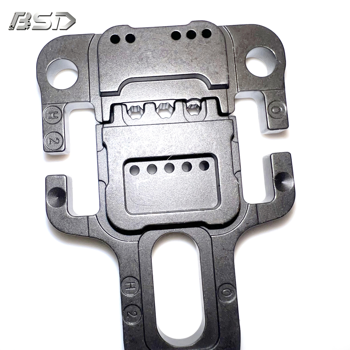
Choosing a manufacturing process requires comparing geometry, volume, tolerance, material performance, and total cost. MIM is not always the best option for every metal part, but it becomes highly competitive when the component is small, complex, and produced in large quantities.
CNC machining is suitable for prototypes, low-volume production, and parts requiring extremely tight tolerances from billet material. However, CNC becomes expensive when parts have thin walls, micro-features, undercuts, or multiple complex surfaces.
MIM offers better scalability for complex geometries. Once the mold is completed, the same complex shape can be produced repeatedly with stable quality and lower unit cost.
Investment casting is suitable for larger metal parts and medium-complexity components. However, it may struggle with very small features, thin walls, and tight as-formed tolerances.
MIM uses injection pressure to fill fine details in the mold cavity. This gives it better capability for miniature parts, thin-wall structures, and precision components.
MIM requires initial tooling investment, so it is more suitable for medium-to-high volume production. When annual demand is stable and the part geometry is complex, the tooling cost can be amortized quickly.
For small batches, CNC machining may remain more economical. For high-volume complex components, MIM usually delivers stronger cost performance.
| Process | Volume Sweet Spot | Complexity Limit | Surface Finish | Standard Tolerance |
|---|---|---|---|---|
| CNC Machining | Low to medium volume | Moderate to high | Excellent | Very tight |
| Investment Casting | Medium volume | Low to moderate | Moderate | Medium |
| MIM | High volume | Extremely high | Very good | High precision |
MIM supports a broad range of engineering alloys. Material selection depends on corrosion resistance, strength, magnetic performance, wear resistance, and application environment.
Stainless Steel: Common grades include SUS304L, 316L, 17-4PH, 420, and 440C. These materials are widely used in medical, consumer electronics, industrial, and structural components.
No Nickel Material: Nickel-free materials such as PANACEA and F75 are suitable for applications requiring biocompatibility or nickel-sensitive environments.
Magnetic Materials: Typical magnetic alloys include FeSi3, FeCo50, FeCo49V2, and Fe-50Ni. These are used in electromagnetic, sensor, actuator, and precision magnetic components.
High Strength Steel: Materials such as X-81 and HHSXX are selected for high-strength, wear-resistant, or load-bearing applications.
Low Alloy Steel: Materials such as Fe-2Ni, Fe-4Ni, and Fe-8Ni offer a balance of toughness, strength, and cost efficiency.
MIM parts can achieve high density and excellent mechanical properties after sintering. The final performance depends on powder quality, binder formulation, debinding stability, sintering atmosphere, and heat treatment.
For many applications, MIM components can replace machined or cast parts while offering better geometry freedom and production efficiency.
MIM is most suitable for small and complex parts. Very large parts, extremely thick sections, or low-volume projects may not be ideal. Wall thickness should be controlled carefully to prevent distortion, cracking, or internal defects during debinding and sintering.
Successful MIM production depends on early Design for Manufacturability analysis. Engineers should design the component with molding, debinding, sintering shrinkage, and post-processing in mind.
Uniform wall thickness is strongly recommended. Consistent wall sections help achieve stable mold filling, uniform debinding, and predictable sintering shrinkage.
Thick sections should be cored out where possible. Coring reduces material usage, lowers defect risk, and improves dimensional stability.
MIM parts require proper draft angles for mold release. Sharp internal corners should be avoided because they increase stress concentration and may cause cracks during sintering.
Generous radii improve feedstock flow, reduce stress concentration, and enhance part strength.
MIM is a near-net-shape process, but secondary operations are often used when specific functional areas require tighter control.
Common secondary operations include:
Post-Machining: for critical dimensions, bores, slots, and mating surfaces.
Tapping and Threading: for precise internal or external threads.
Surface Finishing: including polishing, blasting, passivation, coating, or plating.
Heat Treating: for improved hardness, strength, and wear resistance.
Selecting the right Metal Injection Molding manufacturer is critical. A qualified manufacturer should have strong material formulation capability, mold engineering experience, stable sintering technology, and reliable quality control.
A capable supplier should understand feedstock formulation and powder-binder compatibility. Proprietary feedstock recipes improve process stability and final part quality.
Mold design is critical because MIM parts shrink during sintering. The manufacturer must understand shrinkage compensation, gate location, venting, mold flow, and dimensional correction.
A professional MIM supplier should use inspection systems such as CMM, metallographic analysis, density testing, hardness testing, tensile testing, and surface inspection. For regulated industries, ISO quality systems and application-specific certifications are also important.
Metal Injection Molding is a highly scalable manufacturing technology for small, complex, and high-volume metal components. It combines the design freedom of injection molding with the strength and durability of metal materials.
Its key advantages include proprietary feedstock formulation, strong mold development capability, stable sintering technology, and mature post-processing options. With materials such as stainless steel, nickel-free alloys, magnetic alloys, high-strength steel, and low-alloy steel, MIM can serve a wide range of demanding industries.
For parts requiring complex geometry, thin walls, high repeatability, and stable mass production, MIM is often a more efficient and cost-effective manufacturing solution than traditional machining or casting.
A: Standard as-sintered tolerances generally range from ± 0.3% to ± 0.5% of the nominal dimension. Smaller dimensions naturally hold tighter absolute variations. If your application requires extreme precision beyond this range, you can easily perform secondary CNC machining on the final dense part.
A: This depends entirely on your chosen base alloy. The process itself does not alter fundamental magnetic properties. For example, parts molded from 17-4 PH stainless steel are highly magnetic. Conversely, components made from 316L stainless steel remain completely non-magnetic.
A: Yes. Because the final components achieve 96 to 99 percent theoretical density, they behave exactly like standard wrought metals. You can subject them to standard hardening processes, electroplating, physical vapor deposition (PVD) coating, and chemical passivation without issue.
A: Tooling timelines depend on geometric complexity and mold cavitation. Typically, you should expect 4 to 8 weeks for complete mold design, tool steel fabrication, and the delivery of the First Article Inspection (FAI) samples. Subsequent production runs happen rapidly.


