

Views: 0 Author: Site Editor Publish Time: 2026-07-01 Origin: Site


Modern manufacturing is shifting rapidly toward high-stakes metal fabrication. In these demanding environments, dimensional accuracy is absolutely non-negotiable. Even microscopic deviations can trigger catastrophic mechanical failures down the line.
Procurement and engineering teams often face a difficult tradeoff. You must constantly balance aggressive timelines, strict compliance tolerances, and shrinking project budgets. Finding a path satisfying all three constraints feels virtually impossible.
This guide breaks down the mechanical realities behind the Computer Numerical Control process. We will outline exact evaluation criteria for producing precision metal parts. You will also discover a clear framework for shortlisting a qualified production partner to ensure repeatable success.
CNC machining is a subtractive, software-driven process critical for achieving tight tolerances (often up to ±0.0005 inches) in robust metal alloys.
The primary ROI of CNC lies in absolute repeatability—ensuring part #1,000 is identical to part #1 without tool degradation impacting spec.
Cost drivers are tied directly to design complexity, multi-axis requirements, and material selection, requiring strategic DFM (Design for Manufacturing) evaluation.
Choosing the right CNC machining manufacturer hinges on verifying their quality assurance infrastructure (e.g., CMM capabilities) and compliance certifications (e.g., ISO 9001, AS9100).
At its core, CNC Machining relies on a subtractive manufacturing methodology. You start with a solid block or billet of raw material. Specialized machinery then selectively removes material to reveal the final shape. Pre-programmed software dictates every single movement. The machine interprets digital instructions to control cutting tools precisely.
Operators do not manually guide the cutting instruments. Advanced computer systems translate engineering designs into automated mechanical actions. This eliminates human error during the physical cutting phase.
Two primary modalities dominate the factory floor. Engineers select the specific method based on part geometry.
CNC Milling: This process uses rotating cutting tools to remove material from a stationary workpiece. It is best for complex, flat, or highly asymmetric geometries. The cutting tool moves across multiple axes to carve out intricate features.
CNC Turning (Lathes): This method rotates the workpiece at high speeds while a stationary cutting tool shapes it. It remains optimal for cylindrical components. You achieve high-speed symmetry and excellent surface finishes on round parts.
Modern manufacturing thrives on digital integration. CAD (Computer-Aided Design) files represent the ideal digital version of a part. CAM (Computer-Aided Manufacturing) software translates this design into machine-readable G-code.
This CAD/CAM integration creates a powerful "digital twin" of your product. It removes manual operational variances entirely. You establish a direct, verifiable link between the original engineering file and the finished metal part. What you design on the screen is exactly what emerges from the machine.
Demanding industries require absolute certainty. Secondary operations often introduce unacceptable variability. When you machine a part directly from raw stock, you establish a highly controlled baseline.
Manual fabrication simply cannot match modern software-driven equipment. Automated cutting systems achieve incredibly tight tolerances. You can often specify dimensions within ±0.0005 inches.
Statistical process control (SPC) plays a crucial role here. Factories track dimensions across large production runs. The data proves predictable failure rates remain astonishingly low. Part number one matches part number one thousand perfectly.
Engineers love subtractive manufacturing because it handles tough materials easily. Thermal processes like 3D printing often alter the physical properties of metals. Cutting away material preserves the original structural integrity of the alloy.
Aluminum (6061/7075): Excellent strength-to-weight ratio. Highly machinable and ideal for aerospace or automotive components.
Stainless Steel (304/316): Known for superior corrosion resistance. It requires rigid tooling but yields incredibly durable medical and food-grade parts.
Titanium: Offers extreme temperature resistance and biocompatibility. Machining it requires specialized feeds and speeds to prevent work hardening.
Inconel: A superalloy capable of surviving extreme jet engine environments. Only highly rigid equipment can process this material successfully.
Hardware development carries significant transition risks. Prototyping a part using one method and mass-producing it via another invites disaster. Late-stage qualification failures ruin project timelines.
Subtractive manufacturing solves this scalability problem. You can cut prototypes using the exact same material intended for mass production. You also use the exact same manufacturing process. Engineering teams validate the mechanical properties early, entirely eliminating late-stage surprises.
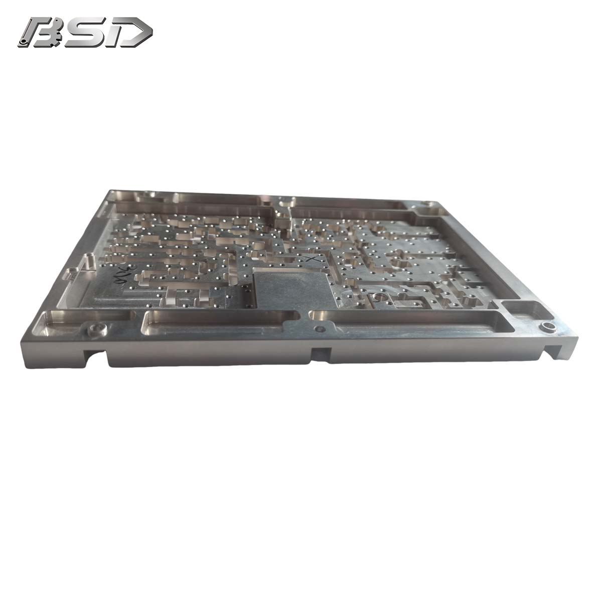
Selecting the right production process requires objective comparison. Different fabrication methods serve entirely different engineering needs. Procurement teams must map features directly to required business outcomes.
Understanding where automated cutting excels helps you allocate resources effectively. Let us examine how it stacks up against competing technologies.
| Fabrication Process | Primary Advantage | Ideal Production Volume | Best Application Scenario |
|---|---|---|---|
| Subtractive Machining | Extreme precision and high material strength | Low to mid-volume (1 to 10,000 units) | Functional metal prototypes and end-use structural parts |
| Metal 3D Printing (DMLS) | Unlimited internal geometric complexity | Prototyping to very low-volume | Lattice structures or complex internal fluid channels |
| Die Casting | Rapid cycle times for identical parts | Extreme high-volume (100,000+ units) | Consumer goods or large automotive runs |
When evaluating CNC Machining versus Metal 3D Printing (DMLS), the subtractive route wins decisively on unit efficiency at scale. It delivers superior surface finishes directly off the machine. The structural density of billet metal remains unmatched. You should reserve 3D printing strictly for impossible internal geometries.
Comparing against Die Casting reveals another sharp contrast. Casting requires massive upfront tooling investments. Subtractive manufacturing requires zero upfront mold costs. This makes it the lower-risk choice for low-to-mid volume runs. It also supports designs subject to ongoing iteration. Casting only achieves positive returns at extreme high volumes.
Many procurement professionals assume automated machining is always the most expensive route. This assumption frequently proves false. You must consider the entire production lifecycle.
Reduced secondary finishing lowers the final bill significantly. The complete absence of expensive molds offsets higher hourly machine rates. When you factor in the speed of iteration, subtractive methods often present a leaner overall project budget.
Optimizing your design before hitting the factory floor prevents budget overruns. Engineers must understand how specific geometry choices impact machine cycle times.
Ignoring DFM principles exponentially increases your cycle time. Deep cavities are a primary offender. Tools must reach deep into the metal, increasing the risk of vibration or deflection. This forces operators to slow down feed rates considerably.
Non-standard radii also cause major headaches. If an internal corner does not match a standard end-mill size, the machine must work harder to clear the material. Furthermore, applying unnecessarily tight tolerances across an entire part drives up inspection time.
Selecting the right machine architecture directly influences your timeline. Here is a clear decision matrix for evaluating axis requirements.
| Criteria | 3-Axis Systems | 5-Axis Systems |
|---|---|---|
| Geometry Capability | Simple, mostly planar surfaces | Highly complex, contoured geometries |
| Setup Requirements | Multiple manual repositionings required | Done-in-one setup (minimal handling) |
| Hourly Operating Rate | Lower base rate | Higher base rate |
| Overall Efficiency | Cost-effective for basic brackets | Reduces total time for complex parts |
A 3-axis system represents a highly cost-effective approach for simpler parts. The machine moves along the X, Y, and Z axes. Conversely, 5-axis systems add rotational movement. They reduce setup time and custom fixtures for complex geometries. However, they naturally carry a higher hourly rate.
Actual delivery schedules depend on more than just cutting time. Sourcing exotic metal grades often adds weeks to your timeline. Custom tooling requirements for unique threads or undercuts also delay project kick-offs.
Post-processing treatments represent another major hidden variable. Anodizing, powder coating, or specialized heat treating all require additional transit and processing time. You must factor these secondary steps into your initial schedule.
Handing over a critical project requires absolute trust in your vendor. You need concrete proof of their operational maturity before issuing a purchase order.
A reliable CNC Machining manufacturer must prove their quality assurance setup. Visual inspections are insufficient for high-stakes parts. You must verify they own and operate advanced measurement equipment.
Look specifically for Coordinate Measuring Machines (CMM). These devices use probes to verify exact dimensions against the original CAD file. You should also look for optical comparators. Always request sample First Article Inspection (FAI) reporting formats during your vetting phase.
Regulated industries demand rigorous documentation. If you build components for the medical, aerospace, or automotive sectors, trace data is mandatory. Establish rigid compliance baselines early.
Require verifiable ISO certifications, such as ISO 9001. For aerospace, demand AS9100 credentials. You must also insist on Material Test Reports (MTRs). A competent factory will maintain full lot traceability from raw metal intake through final shipment.
Equipment failure happens in every factory. How your partner handles that failure dictates your project timeline. You must evaluate their entire machine park carefully.
A vendor operating multiple redundant machines for specific operations drastically reduces risk. If a primary milling center goes down, they can seamlessly shift your job to an identical machine nearby. This redundancy prevents unforeseen project delays.
Vague inquiries generate vague estimates. You need a highly structured Request for Quote (RFQ) package to secure accurate project data. Follow these best practices to formalize your request.
Supply Native 3D CAD Files: Provide STEP or IGES formats so the vendor can run accurate CAM simulations.
Include 2D Drawings: Clearly call out critical tolerances, tapped holes, and surface finish requirements. Do not over-tolerance non-critical features.
Define Material Callouts: Specify exact alloy grades and acceptable material alternatives to speed up quoting.
Provide Volume Tiers: Request quotes across multiple quantities (e.g., 50, 500, 5000) to understand their scaling efficiencies.
Automated subtractive manufacturing remains the absolute gold standard for precision metal components. It consistently delivers the high strength, tight tolerances, and strict repeatability modern engineering demands. No other process transitions so smoothly from early prototype validations directly into scalable mass production.
Moving forward, we recommend auditing your current metal part designs specifically for subtractive optimization. Identify features driving up cycle times and remove them. Gather your detailed CAD files and 2D drawings. Finally, reach out to a vetted production partner to request a thorough DFM review and an initial pilot run quote.
A: Lead times vary based on design complexity, raw material availability, and current machine capacity. Standard components typically range from 3 days to 4 weeks. Specialized alloys or complex post-processing steps, such as hard anodizing or heat treating, will add extra time to the final delivery schedule.
A: Tighter tolerances directly drive up project costs. They require specialized cutting tools, significantly slower feed rates, and rigorous manual inspection protocols. This increases total machine cycle time and labor hours. You should only apply ultra-tight tolerances to critical mating features to maintain an efficient project budget.
A: Yes, many capable facilities manage both phases. However, you must carefully evaluate their internal setup. Ensure they maintain dedicated prototype cells completely separate from their high-volume automated lines. This separation prevents disruptive scheduling bottlenecks and ensures rapid iteration without delaying large ongoing production runs.


